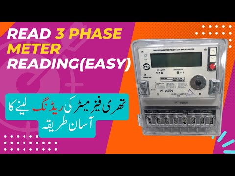
It shows the basic technical information about the meter and its serial number. Each meter is assigned a unique individual serial number, and the first four digits are the meter code followed by a six digit serial number. These indicate the active voltage presents of each phase.
Q. What is CT in meter?
CT (Current Transformer) Meters are installed on any connections with a load greater than 100 Amps. A CT meter only measures a fraction of the current passing through the connection and a multiplier is applied to this reading to reflect the actual current.
Table of Contents
- Q. What is CT in meter?
- Q. What is the difference between whole current meter and CT meter?
- Q. How does CT Connect to energy meter?
- Q. Why CT and PT are used in substation?
- Q. Why CT is grounded?
- Q. How do you calculate KVA to CT ratio?
- Q. How much current is in 11kV line?
- Q. What is CT and VT ratio?
- Q. What is VT and CT?
- Q. What is difference between CT and VT?
Q. What is the difference between whole current meter and CT meter?
A whole current meter is where the electricity supply passes through the meter itself, while a current transformer (in simple terms an electro-magnetic ring around the wire) or CT meter is where current transformers are used.
Q. How does CT Connect to energy meter?
Key Points
- Install CTs on the phase conductor that corresponds to the voltage input phase.
- Install CTs with the arrow or label ‘This side toward source’ facing towards the breaker feeding the load.
- Connect the white and black CT leads to the corresponding CT input terminals with the white and black dots.
Q. Why CT and PT are used in substation?
Instrument transformers (CTs and PTs) supply protective relays with current and voltages of magnitude proportional to those of the the power circuits. Instrument transformers helps in attaining different types of secondary connections to obtain the required current and voltages.
Q. Why CT is grounded?
Why CT secondary is grounded? The one pole of the CT is earthed to avoid voltages being present due to capacitive coupling between the CT secondary and the line being monitored (CT Primary). At low voltages CT Secondary is not earthed but this is always the case with 11Kv and above.
Q. How do you calculate KVA to CT ratio?
Calculate the CT ratio. The CT ratio is the inverse of the voltage ratio. In this example, the voltage ratio is 1:5, so the CT ratio is 5:1. This means the current level is stepped down 5 times where, if the primary current is 200 amps, the CT output is 40 amps.
Q. How much current is in 11kV line?
An 11 kV distribution circuit may carry 150 A in each of its three phases, thus transmitting a power of 3 MW. A 400 V final distribution circuit may carry 200 A in each of its three phases, thus transmitting a power of 150 kW.
Q. What is CT and VT ratio?
Generally, when measuring high voltage and high current transformer signals, you use a VT (voltage transformer) and CT (current transformer). For example, if the rated primary current/rated secondary current is 500 A/5 A, the CT ratio is 100. The same holds for VT. If not using a VT or CT, each ratio is 1.
Q. What is VT and CT?
Generally, when measuring high voltage and high current transformer signals, you use a VT (voltage transformer) and CT (current transformer). The ratios between the primary and secondary rated voltages and rated currents are the VT and CT ratios.
Q. What is difference between CT and VT?
One of the major difference between them is that the current transformer converts the high value of current into low value whereas the potential or voltage transformer converts the high value of voltages into low voltage….Comparison Chart.
| Basis for Comparison | Current Transformer | Potential Transformer |
|---|---|---|
| Impedance | Low | High |